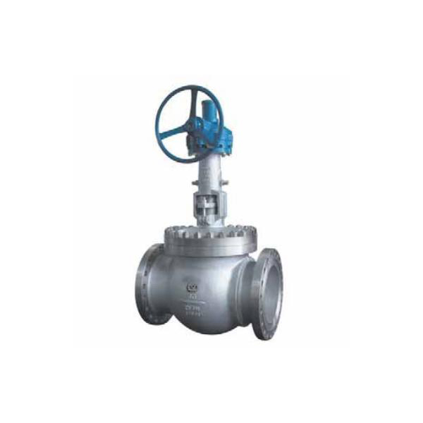
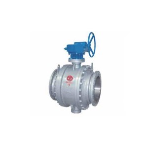
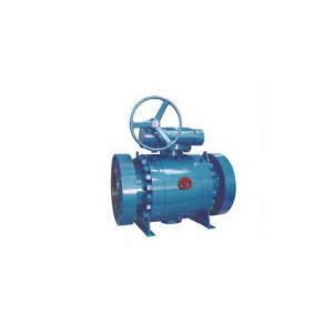
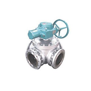
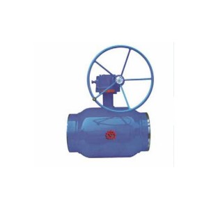
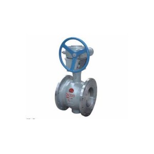
High Performance Track Ball Valve Series
Performance Specification
| Pressure | Testing pressure at constant temperature (MPa) | Applicable temperature | Applicable medium | |||
| The shell testing | High-pressure seal | Low-pressure seal | ||||
| Nominal rating pressure(PN) | 1.6 | 2.4 | 1.76 | 0.6 | -29~121℃ or upon the user requirement |
Natural gas,liquefied gas,coal gas,oil,water, requirement |
| 2.5 | 3.75 | 2.75 | 0.6 | |||
| 4.0 | 6.0 | 4.4 | 0.6 | |||
| 6.4 | 9.6 | 7.04 | 0.6 | |||
| 10.0 | 15.0 | 11.0 | 0.6 | |||
| 16.0 | 24.0 | 17.6 | 0.6 | |||
| Pressure classes(Class) | 150 | 2.94 | 2.16 | 0.6 | ||
| 300 | 7.67 | 5.62 | 0.6 | |||
| 400 | 10.2 | 7.48 | 0.6 | |||
| 600 | 15.3 | 11.23 | 0.6 | |||
| 900 | 23.0 | 16.85 | 0.6 | |||
| 1500 | 39.0 | 28.6 | 0.6 | |||
Its main structural features are:
1. Static single seat structure. It can ensure that the two-way seal is tight, reliable and zero leakage.
2. Top mounted design enables the system to be maintained online.
3. The cam mechanism at the lower end of the valve stem can provide a mechanical wedge tightening force to ensure continuous tight sealing.
4. The opening and closing process is completed in two sections. The lifting stroke is short and easy to operate.
5. During the opening and closing operation, the sealing surfaces are completely out of contact, without wear, with short operating torque and long service life.
6. The space formed by the ball and the valve seat during the rotation process makes the medium flow rate in the channel increase, so as to achieve the function of cleaning and sealing.
7. The fire resistance design of the ball valve shall comply with the provisions of api607, api6fa, JB / T 6899 and other standards. Once a fire occurs and the soft seal diagram is burnt, the fire protection structure of the ball valve can prevent a large amount of leakage of media. To prevent further expansion of the fire.
8. The valve driving device includes manual, worm gear and worm drive, and electric. The electric valve is easy to realize automatic control, easy to operate, safe and reliable.
Technical Specification
| Design standard | GB | ASME |
| Face to Face | JB/T 7745GB/T 12221 | ASME B16.10 |
| Flanged Size | GB/T9113JB/T79 | ASME B16.5MSS SP44 |
| Butt-welding ends | GB/T12224 | ASME B16.5 |
| Test & inspection | JB/T9092 | API598 |
Note: The sizes of valve connection flange and butt-welding end can be designed according to customers requirement.
Major Parts Material Form
| No. | Accessory name | Material | |
| GB | ASTM | ||
| 1 | Body | WCB | A216-WCB |
| 2 | Gasket | Graphite+stainless steel | Graphite+stainless steel |
| 3 | Bushing | Nkoalium PTFE | Nkoalium PTFE |
| 4 | Sealing ring | PTFE STEEL | PTFE STEEL |
| 5 | Ball | WCB+HCr/STL | WCB+HCr/STL |
| 6 | Pin | 1Cr13 | A276-410 |
| 7 | Stem | 1Cr13 | A182-F6a |
| 8 |
Packing |
Flexible Graphite | Flexible Graphite |
| 9 | Packing gland | WCB | A216-WCB |
| 10 | Bearing | Assembled | |
| 11 | Stem nut | ZA19-4 | A439-D2C |
| 12 | Cover | 35 | ANSIC1036 |
| 13 | Hand wheel | QT400-17 | QT40017 |
| 14 | Yoke | WCB | A216-WCB |
| 15 | Fixing pin | 1Cr13 | A216410 |
| 16 | Bonnet | WCB | A216-WCB |
| 17 | Nut | 35 | A194-2H |
| 18 | Stud | 35CrMoA | A193-B7 |


